
Hull Design Defects
Part I
by David Pascoe
This series of articles is written exclusively for marine surveyors to help identify the wide range of structural defects that can be found in boats and yachts. Because there is such a diversity in types of hulls, design styles and an ever-expanding array of new construction materials, it is difficult for surveyors to keep up to date on cause-and-effect evaluations.

Whether the surveyor deals exclusively with prepurchase surveys, insurance claims or marine expert related matters, learning how to locate, detect and evaluate is a critical factor in the surveyor's work. This essay deals with basic principles of hull design, along with cause and effect analysis of hull failures. It will set the necessary foundation for this continuing series of essays.
Primary Cause of Structural Failures
Improper design and the improper selection and use of materials is the primary cause of most non-damage related structural failures. Contrary to common belief, actual manufacturing defects only rarely figure into structural failures. It should come as no surprise to any surveyor that the boat building industry, much like the automotive industry which, after more than 70 years of mass production, backed up with their enormous financial resources, is still fraught with frequent design defects. But unlike the automotive industry, boats are not manufactured in units numbering millions, rather 10's and 100's at best.
Because of this, design faults are spread over a very wide array of different builders and tens of thousands different models over the years so that rarely do major design errors ever become widely documented. To make matters worse, there are very few avenues for dissemination of information, and virtually no one who maintains any kind of database on hull failures. This essay will attempt to illustrate the most common defects, the cause and the visible effects that the surveyor can use as a basis for conducting a thorough structural survey.
Structural Principles
Before we go directly into reviewing problems, its important that we first review the major principles of hull design. From and engineering standpoint, fiberglass boats have similarities to both bridges and aircraft airframes. A discussion of these similarities will help us to better understand the forces that act on a boat hull, and the structural principles required to build one.
Boats are similar to bridges in that the hull must have a framing system to support it because the hull itself, like a bridge, spans a fluid substance. Whereas a bridge spans air, a hull spans water, and while water is more dense, it is still a fluid and offers lesser means of support that solid ground. Further, when a boat is hauled out and set on blocks, often only one at each end of the hull, that hull then literally becomes a bridge spanning open air. Unless the hull has an adequate system of framing and girders to span the unsupported sections, like a bridge it will buckle and collapse.
We can add to this the fact that boats are dynamic objects; they often travel at high speeds over rough water and even occasionally, if not frequently, become airborne. Thus, the stresses on a boat hull are far more than a matter of just gravity and mass, but are multiplied by velocity and compounded by slamming. And as anyone who has ever done a belly-flopper off a diving board knows, water becomes hard as a rock when a wide, flat object falls upon it squarely.
Most bridges do not consist of a flat deck supported by girders underneath. Rather, most bridges are either in the form of a truss, or they are suspended from above by a combination of rigid and flexible supports. A boat is also similar to this principle since the hull bottom and sides do not alone constitute the entire structural framework. Boats that lack weather decks and superstructures, for example, are far weaker than their cousins who do have these additional structures. Thus, decks and superstructures also constitute major structural elements of most boats and ships.
And here it is that fiberglass boats develop similarities to modern jet aircraft. Aircraft utilize the principle of monocoque construction. That is, the body of the aircraft does not have a frame but essentially is the frame. The skin of the aircraft and the framing system are so closely integrated that they essentially become one structure and its hard to tell where one ends and the other begins. Modern jet aircraft are essentially flying pipes with wings, and it is from this engineering principle that they gain their strength, despite the extremely light construction.
Modern fiberglass boats make use of this principle of monocoque construction and in this way are more closely related to aircraft than they are to their wooden-boat ancestors from which they evolved. A wood boat is the sum of its many parts while a fiberglass boat hull is essentially one component. The combination of molded hull and deck joined together creates a unified whole that is much stronger than the sum of its parts. But boats are proportionately far heavier than aircraft and are subjected to different stresses. Aircraft don't fly off the tops of waves; boats do. While the bottoms of hulls take the major brunt of stresses, and must be designed to withstand them, the monocoque construction still plays a major role in providing strength to the overall structure.
There is no better illustration of this than the offshore racer type boat, a long skinny hull equipped with tremendous horsepower. In the so-called "cigarette" type boat, the deck provides a major part of the hull strength that, lacking a strong deck, the hull would buckle. These decks are not "hull covers" but designed as structural elements. These race boats are true monocoque structures because the hull and deck structures are not screwed or bolted together, but literally bonded together to become one piece.
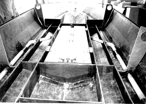
Here's a good example of poor design and construction detail. Utilizing a glass over plywood framing system, there are no fillets under the frames or stringers which are butted hard against the hull. This creates hardspots with the propensity for stress cracking. In addition, the length-to-height ratio of the tall stringers creates instability where the stringers are likely to buckle under inpact loading. Additional framing between the stringers is needed to stabilize them. Also note that there are only two hull side stiffeners so that flexing of the sides is likely to cause hull/deck joint breakage. In the forward section, a dog leg in the stringer profile can be seen.
Dynamics of Hul Stress
Power boat hulls are essentially modified rectangles with a shallow vee on the bottom. When a boat falls off, or slams down off a wave, the bottom impacts the water and suddenly stops its downward movement. This sudden stop sends shock waves up the hull sides that are then transmitted to the deck and any upper structures that may exist. In the meantime, while the hull suddenly stops its downward movement, everything inside the hull wants to continue on downward, creating even more stress.
When the hull impacts the water, the resultant stresses work to cause the hull to want to buckle transversely and longitudinally. The impact with the water is never uniform along the length of the hull so that one end, or one side, of the hull is more stressed than the other. One effect is to try to break the boat in half like snapping a stick in half. The other effect is to bow the hull sides inward or outward, the effect of bending along the horizontal plane. Yet another is twisting or torsional stress along the entire length of the hull.
In actual operation under heavy conditions, the hull sides of most boats will deflect to greater or lesser degrees depending on how well it is designed. This is the result of impact loading, bending and torsional loading on the hull caused by high velocity over waves, porpoising and so on. If you've ever wondered why so many boats have rub rails falling off and weak and damaged hull/deck joints, you probably thought that this was primarily due to hitting up against dock pilings. But the real reason is that many boats have poorly designed hull/deck joints that are simply lap joints screwed together. It is the stress transferred from the hull bottom to the hull sides and thence to hull/deck join that causes the screws that join these parts together to break loose. Putting screws into fiberglass is a terrible means of making connections. Screw joins are simply too weak to work effectively.
So it is that the deck - and the superstructure that is often integral with the deck, i.e., are molded as one piece - are not only part of a unified structure, but also absorb much of the load initially induced on the hull. This also accounts for much of the damage and cracking found in and around deck structures, and why on many boats windows, doors and hatches and portholes just never seem to stop leaking. The whole structure is working so that no amount of caulking, bedding and gasketing can ever stop the leaks because they just open up again
These are the effects of stress on the exterior boat hull and structure. But the stress doesn't end there for we've not yet considered the hull framing system. The framing system consists of stringers, bulkheads and frames in more conventional construction. Yet increasingly builders are seeking to reduce costs and streamline production by eliminating much of the detail work involved in the framing system. They are doing this by again utilizing the principle of monocoque construction which takes the form of premolded "liners" or so-called 'grid liners," a premolded combination internal framing system and accommodation components. And rather than bonding these parts together with conventional tabbing or taping, instead they are being glued together with some sort of adhesive putty.
Although the use of liners has been around for a long time, the combining of a framing system with a liner is new. And as any experienced surveyor can see, it poses some obvious problems, but that's a subject I'll deal with in Part II. In the meantime, the conventional stringer, bulkhead and frame system is the method used by about 98% of all boats over 30 feet.
Stringers
In power boats, stringers provide the majority of the longitudinal hull resistance to bending in the vertical plane. The apex of the vee at the bottom or keel adds additional strenght. This is qualified by whether the deck is also designed to give the hull longitudinal rigidity. Depending on design, some decks, particularly on motor yachts with very short decks and lots of windows, are so small as to add very little additional strength. On the other hand, the typical flybridge sport fisherman with its long foredeck, relatively small windows and strong house sides, adds a great deal of rigidity to a hull. So it is that we can now understand why there is a lot more to the strength of hull than just the framing system. In monocoque, or semi-monocoque construction, the whole structure must be considered. And it is precisely here that so many untrained "designers" who lack a solid background in engineering, make their mistakes.
Mistakes involving stringer design and installation are legion, about which a whole book could be written. And yet the principles for creating an effective stringer system are very simple and easy to achieve. Surely there are not many designers or builders who do not understand this. Or are there? Problems usually arise as a result of other design and marketing considerations. Typical examples are when a designer wants to create a small boat with 6'6" headroom or wants to install unusually large engines. The machinery spaces, which are not subject to appearance and marketing considerations, are usually sacrificed.
In order to get the 6'6" head room or make high profile engines or other equipment fit, the principles of proper stringer design are often sacrificed. In other words, the principles of sound hull design get sacrificed for marketing considerations and the surveyor needs to be constantly aware of this fact. Its the primary reason why, in this day when all is known how to build a good boat, bad boats are still being built. Give the customer what he wants, even if the product is going to fall apart.
The principles of good stringer design are simple. They must run uninterrupted from one end of the hull to the other. They must be of adequate height to width ratio, i.e., structural modulus, to resist impact loading on the hull skin, be of sufficient strength to carry the engine load, be stabilized against lateral movement if high profile, and be securely attached to the hull so that they don't break loose. The profile, or top of the stringer, should run in a straight line. If there are any changes in the profile, then special design reinforcements must be added.
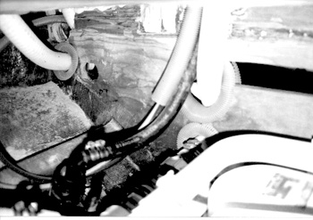
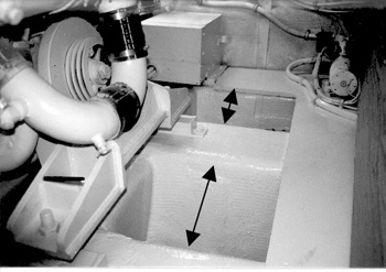
Dog leg in stringer which was cut down to make the engine fit. The stringer proved to be so weak that the engine bounced every time the hull hit a wave, ultimately bending the shaft and wrecking the transmission. Also notice the hard spots created by the fuel tank mounting pads at top of photo that caused stress cracks in the hull.
These principles are often compromised by designs that utilized dog-legs, step downs, step ups (meaning an inconsistent profile along their length), perforations with large and ill-placed holes, inadequate section modulus and numerous other faults. In nearly all the cases that I have seen, there is no compelling reason why these faults should have occurred. What these design faults unfortunately suggests is that the designers really don't understand the basic engineering principles. Yet in most cases of failure that I have seen, the builder could have had his cake and eat it too by giving a little more thought to the problem. What is compromised in one way can always be built up in another. There's always an alternative solution. The builder just didn't take the time to consider it.
Bulkheads
serve two very distinct functions. First, bulkheads act as transverse frames. More importantly, the bulkhead is the structural element that prevents torsional stress or twisting of the hull. Unified with a stringer system, they form a structural web and a truss. Remove the bulkheads and its rather like removing the trusses from a bridge or a roof. The overall strength can be reduced to the point of structural failure. And because of the efforts of interior designers to produce small boats with the appearance of wide open interior spaces by the elimination of full, and even partial bulkheads, that hull structures begin to fall apart.
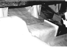
Here's what often happens when a large cut out is made in a structural bulkhead. In this case, the 3/4" plywood was fractured in three places.
One builder that produced a 34 footer which had only one partial internal bulkhead - an engine room bulkhead that was only slightly more than half the height of the freeboard of the hull - resulted in severe structural failures in much of the model line. You probably know the boat, the 34 Wellcraft Grand Sport. In this model line, not only did major hull skin and stringer failures occur, but in many cases the single plywood bulkheads fractured from side to side.
Even companies with reputations for building very rugged hulls occasionally make silly mistakes. In a nearby photo you will see the result when Bertram decided to make very large cut outs in the centers of plywood bulkheads to save weight. They unthinkingly removed all the strength from the plywood bulkhead with predictable results; the bulkheads fractured.
And we know how engine room fore and aft bulkheads constitute one of the foremost structural elements of medium size yachts, and we've witnessed what happens the builder unthinkingly decides to cut a big hole in the bulkhead and install a door. For whatever reason, it did not occur to the builder or designer that he was destroying the structural integrity of the bulkhead.
This is another good example of the structural integrity of a bulkhead being defeated by cutting it full of holes. It is perforated like a postage stamp and is destined to fail.
To do their job, bulkheads must be adequately secured to the hull bottom, sides and underside of the deck. Judging by 30 years of inspecting fiberglass boats, its a fair statement to say that many builders don't think that this is very important considering the large number of bulkheads that surveyors find to be broken loose. Probably at least half of all boat builders don't tie the bulkhead to the deck, and often for good reason. The bottoms of their boats are so flexible that the bulkhead will telegraph the deflection of the hull into the deck, causing damage to the deck. Therefore, if they leave a gap at the top, at least it won't tear the deck apart, just everything else that the bulkhead is attached to, or is attached to it.
While we've been talking so far about structural bulkheads, bulkheads come in several varieties, including full, partial and nonstructural partitions. While I know of no published rules on the subject, my own rule is that to be classified as a full bulkhead (1) it must span the width of the hull, (2) span no less than 75% of the depth of the hull and be attached to the bottom, (3) have no openings larger than 50% of the height of the bulkhead, and (4) such openings must be centered in the vertical plane and be adequately strengthened to compensate for the cut out. An opening that effectively cuts the bulkhead in half is not a full bulkhead but a partial. For maximum effectiveness, the bulkhead must be attached to all four sides of the hull.

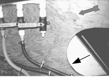
Floor frames under main mast of large sail boat. Properly designed by the designer, the builder apparently saw nothing wrong with drilling the frames full of holes. Here you can follow the fracture along the perforated effect of the holes at right and left sides. Frame was so weakened that ply separation also occurred. A marine surveyor got sued because he either did not find or report this condition, which was far more extensive than this photo shows.
Partial bulkheads are really nothing more than frames and do not serve any greater function than frames. It is a mistake to call a hull partition with two doors in it a bulkhead, for it is really only a partition, or a partial bulkhead at best. Surveyors often mistake partitions for bulkheads. Remember that to be classified as such, a bulkhead must be serving the purpose of tying the four sides of the hull together (bottom, deck and sides). If its shot full of holes and openings, its not achieving that purpose.
Partitions simply serve the function of separating one space from another while providing little, if any major structural strength. Builders often make the mistake of thinking that partitions are structural bulkheads and this is because they don't have any trained engineers or designers on staff. And just because a partition may be taped into the hull does not mean that its structural; the taping is usually there just to hold the partition in place, not the partition to hold the hull together. Sail boats and some smaller power boats often have plywood partitions that are screwed to bosses on an inner liner. Again, these should not be mistaken for bulkheads.
Frames
Frames serve the purpose of stiffening panels between bulkheads and stringers. Fiberglass boats often lack frames where they are needed. Obviously, if a panel is flexing too much, additional framing would prevent that condition. Some builders scrimp on frames because frames create additional detail work and adds more to labor cost. Fortunately, where excessive panel weakness is discovered, adding frames after the fact is usually fairly easy to accomplish. So long as there is accessibility, correcting panel weakness is usually not difficult or costly.
Rigid or Flexible Hulls
Aluminum and steel boats are examples of vessels built to be completely rigid. By the nature of the material, these hulls will not tolerate flexing. Fiberglass boats, however, are another story. Fiberglass boats can be designed to be either flexible or rigid. For example, if you examine Bertram hulls built over the years one can see a very abrupt change in hull design philosophy. Somewhere in the mid 1980's, Bertram made a transition from very rigid hulls to fairly flexible hulls. And as the Bertram engineers have proved from years of extensive R&D (they were one of the few boat builders that took R&D seriously) you can build light, floppy hulls without danger of them falling apart. Moreover, there is a legitimate need to attempt to reduce costs by reducing the weight of the most costly materials. All you have to do to see how this is possible is to look at the aircraft industry which has invested billions in R&D.
In recent years, boat builders have been observing and borrowing some of the fruits of this technology. Unfortunately, aircraft and marine design principles, while having similarities, are not the same. Equally unfortunate is the fact that some boat builders attempt to incorporate this new technology directly into their products without any R&D of their own. And herein lies the problem.
It is entirely possible to take just about any hull and reduce its glass/resin content by 25-35%. In fact, back in 1985 I undertook such a project by taking the plans for a 55' Hatteras with a design weight of 72,000 lbs and redesigned to come in at 42,000 pounds, including a huge 50% reduction in the weight of the basic hull structure. This was done by applying basic airframe design with modifications for marine. The end result had two serious problems that were anticipated. First, the hull weight was reduced by means of an intricate framing system. The problem with that was that anything that was saved on materials cost was more than offset by increased labor costs of achieving the detail work.
Even less did I anticipate the effect on how the hull would handle with a 41% overall weight reduction. Scale model testing revealed the boat to be so light that it would pitch and roll so violently that it would be uninhabitable to human beings. It developed a whip-snap roll in a 3' sea that would literally throw people off the deck. Or when pitching, launch them like a trampoline! So much as for ultra light boats. Weight is a factor that provides stability.
But the project did prove the viability of ultralite, flexible hull construction. Rather like the old Cleveland Browns Rubber Band Defense, designed to bend but not break. The point here is that builders can get away with a lot of shortcuts if they know how to do it right, and if the increased labor costs don't make it impractical. Its easy to design a flexible hull that flexes without breaking. What do I mean by flexible? Well, if on a sea trial you run a tape measure between the top of the engine stringer and the underside of the deck, you'll probably be surprised to see the stringers flexing by as much as 1/2" even on what you consider to be a well made boat. If you were to string diagonal measures from one corner of a large compartment to another, in the manner used to measure squareness of square or rectangular structures, you will find that when you put a boat into a hard turn, one of those measures is going to go very slack. That's because the hull is being twisted by the torsion of the turn.
The early models of the 60' Hatteras Convertible were a prime example of a large hull that was inadequately bulkheaded. These hulls would twist so badly that when you put it into a hard, full speed turn, the propeller shafts would bind up in the bearings. And you can just imagine the effects on shafts, engines and transmissions! This was not so much a matter of a boat with not enough bulkheads, but rather the bulkheads that it did have were poorly designed and executed.
Design-wise, rigid hulls are easier to design and build. With a flexible hull, very rigid attachments of internal components becomes a problem because the flexing starts to tear everything loose. The designer overcomes this by making the interior sort of "free floating." For example, in designing a flexible hull, you do not use the hull or framing system (stringers and structural bulkheads) as a foundation for the interior components such as the sole and cabinetry work. Instead, you build a shelf on the upper hull sides and literally suspend the interior from the shelf. That way when the bottom flexes and the hull sides pant, it doesn't work so hard to tear the interior apart.
Conversely, if the designer is confidant that the hull is rigid, he can go ahead and place the soles on top of stringers (although this is never a really good idea) and attach components to bulkheads or hull sides. For slow speed boats that don't skip across the tops of waves, this is the way its usually done. The hull isn't going to flex that much that its going to rip the interior apart. Whereas the slow boat builder can get away with all sorts of haphazard design, the fast boat builder cannot.
There are limits, of course, to just how far a designer can go with flexibility. In terms of rigidity, we're talking about the difference of the bottom flexing 1/4 to 1/2" or not at all. With the increasing lust for speed and advent of high performance diesels, flexibility causes serious problems. Flexibility is okay for slow or moderate speed vessels, but becomes disastrous to high speed yachts. The reason is not so much inherent in the hull structure itself, but rather in the drive train. Delivering a thousand or more horsepower through a long and large diameter shaft demands higher tolerances of the drive system, and therefore mandates more rigid hulls, not less. Along the length of a 30' drive train, the hull must be absolutely rigid; it cannot deflect or twist lest the whole drive system be thrown out of alignment.
To gain an appreciation for the significance of this, just look at the massive structural system found in high performance Hatteras or Vikings, shown below. When you're dealing with a quarter million dollars or more worth of engines and transmissions, it doesn't pay to fool around. Mistakes are just too costly. On recent survey of a high performance 48 Hatteras and I was absolutely astounded at the massive stringer system in this boat. Although I had seen it before, I didn't really appreciated how large it was. The width of the top hat bottom supports actually covered nearly 50% of the bottom panel area.
Stringer system of a 48' Hatteras Hi Performance Convertible. Note that the width of the top hats are about the same as the width of the bottom panel spans. This is a good example of structural overkill, yet demonstates the builder's concern with strength. Also note the webs between stringers under the engine mounts that provide extra stability. Despite the appearance, these top hats are actually quite thin. When slamming occurs, the thin sections will absorb much of the impact, hence the web sections to increase stability and insure that the engine beds do not move.
Now, did it cost the builder more to do it this way than in the usual way? Not likely, they just had to spend some extra time thinking about what to do. The actual execution and materials cost was probably no higher than any other design. The point here should be painfully obvious; ultimately it costs more to do it wrong that to do it right.
The bottom line is that whether a hull is successfully flexible or rigid is dependent on design and function. In a high speed vessel, everything else about a hull can be flexible, but the foundation of the drive system must be absolutely rigid. Another point to remember is that the smaller the diameter of the shaft, the more bending it can tolerate. Shafts from 1" to 1-1/2" can tolerate a heck of a lot of bending caused by a flexing hull. But when you get up to 2" diameter, these powerful systems will not tolerate movement of the foundation and the systems will begin to self-destruct.
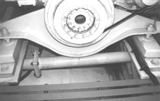
The importance of stringer stability is revealed by this stabilizing strut, in addition to the mounting frame above it. Yacht: 56' Magnum, 2600 HP. With this kind of horsepower, the mounting system and shafts will not tolerate movement.
Material Trends
If you read industry magazines like Composites and Professional Boat Builder, its hard not to be impressed by these advertising vehicles efforts to influence the use of aerospace composites and techniques into boat building. Every issue of these two magazines devotes a major part of its space to promote the use of exotic materials and very complex technology for building pleasure craft. In an industry known for its trial and error, seat of the pants methods of development, one could effectively argue that high technology is probably the last thing this business needs to become involved with.
In my estimation, what they are attempting to do, is to promote and transfer these high tech materials from the aerospace industry, which was backed up by the bounteous source of federal tax dollars, to an industry well known for its critical capitalization problems. They are promoting the very same technology utilized in the production of military war planes such as the F117 and B2 bombers (the later of which has a $2 billion per copy price tag) to the construction of pleasure craft. Viewed in this light, the economics of this trend don't look very promising.
Currently the experimentation with these materials is largely confined to custom boats with very wealthy patrons who are willing to foot the bill in order to posses the latest and greatest. However, there has been some extension into production building, mainly so-called niche markets such as race boats, both power and sail. And to the extent that it is clear that the production boat building industry does not possess the necessary capital resources, nor the profit margins to sustain them, their incorporation of this technology into production building is very likely to continue along the lines of trial and error. What this portends for the surveyor are the risks of failing to locate design failures during surveys, failures involving design, materials and construction techniques that fall into the realm of the experimental. Make no mistake about it, experimentation with new materials directly into a product is the norm, not the exception.
With this basis understanding of the principles of good hull design, we can now begin to study the effects of what happens when these principles are violated.
Related Reading: Hull Design Defects Part II


 Visit davidpascoe.com for his power boat books


David Pascoe is a second generation marine surveyor in his family who began his surveying career at age 16 as an apprentice in 1965 as the era of wooden boats was drawing to a close.
Certified by the National Association of Marine Surveyors in 1972, he has conducted over 5,000 pre purchase surveys in addition to having conducted hundreds of boating accident investigations, including fires, sinkings, hull failures and machinery failure analysis.
Over forty years of knowledge and experience are brought to bear in following books. David Pascoe is the author of:
In addition to readers in the United States, boaters and boat industry professionals worldwide from nearly 80 countries have purchased David Pascoe's books, since introduction of his first book in 2001.
In 2012, David Pascoe has retired from marine surveying business at age 65.
On November 23rd, 2018, David Pascoe has passed away at age 71.
Biography - Long version